Editing POC Details
The pencil icon on the PowerHub home page grid allows the user to edit an individual POC's details.
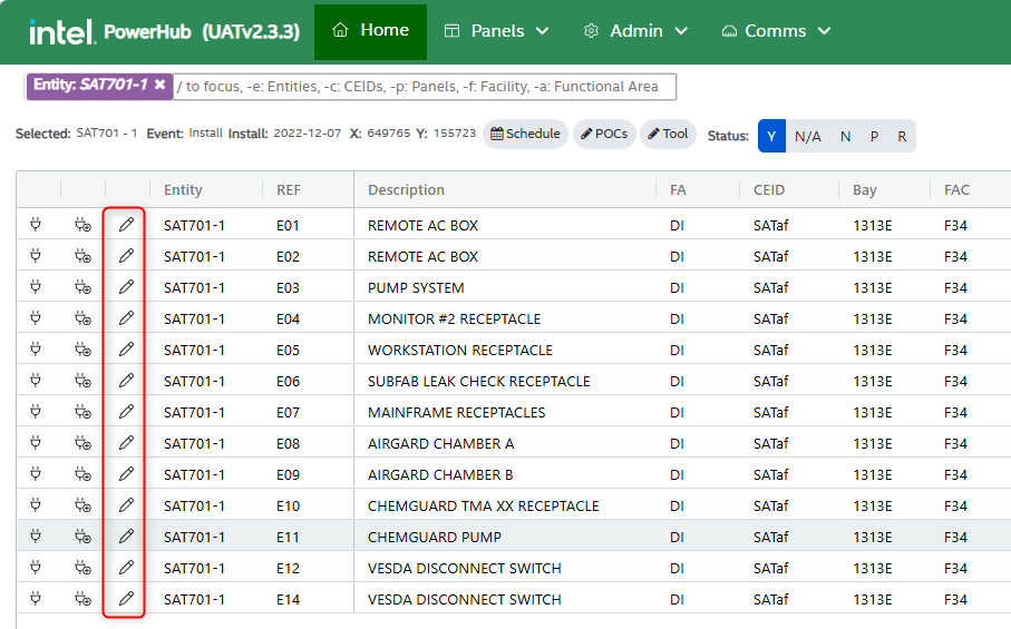
When the user clicks the edit icon in the home grid, the “Edit POC Details” dialog is displayed. Here the user can review and make changes to a POC properties. The Edit POC window fields are as follows:
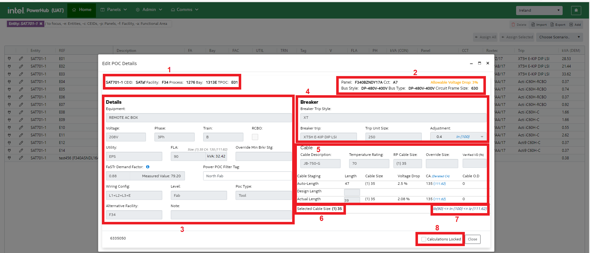
1. Selected POC Details
At the top of the window, there are selected Tool & POC details including:
-
Tool Entity-Life
-
CEID
-
Facility
-
Process
-
Bay
-
TPOC Reference
2. Assignment Details
On the right-hand side of the upper part of the window are panel details (if POC is assigned). These include::
-
Panel ID
-
Circuit (CCT)
-
Bus Style (The panel template that this panel was based on, the panel may have changed since it was first created from the template)
-
Bus Type (Branch, Distribution. Substation)
-
Circuit Frame Size
3. Details
Properties of tool POCs will usually be populated from FaSTr and the user will have no need to change them.
Equipment
This field contains the description of the POC.
Voltage
A drop down list of available voltages, showing the POCs voltage.
Phase
A drop down list of phases voltages, showing the number of hot wires on the load.
-
1Ph – One-phase (One hot wire)
-
2Ph – Two-phase (Two hot wires, referred to as ‘one phase’ in USA but referred to as ‘two phase’ elsewhere)
-
3Ph – Three-phase (Three hot wires)
Train
The power train the POC is on. POCs can only be assigned to panels that have a matching power train. The user can update Train by clicking on the dropdown list and selecting one of the options available.
Cannot be edited if the POC is assigned to a panel.
RCBO/GFCI
Residual Current Breaker with Overcurrent (RCBO) or Ground Fault Circuit Interrupter.
In Ireland, if a circuit is protected with an RCBO, then the ampacities of cables rated at 60oC will be used instead of 70oC.
Utility Type
A drop down list for normal, critical or emergency power.
FLA
The Full Load Amperage (FLA) as per the tool supplier.
The user can edit FLA by typing in the field. Demand kVA is automatically updated when FLA is updated. Connected kVA will also change and is dependent on the demand factor being applied.
Override Minimum Breaker Setting
When a POC assignment is made, a panel and circuit breaker are associated with the assignment.
The Override Minimum Breaker Setting field allows the user to input a figure which overrides the default breaker setting. Where it is known that a circuit may cause nuisance tripping, the user can set this value to ensure that a higher trip unit size/adjustment is selected.
Measured Demand Factor
If a value of measured demand is available form FaSTr then it will be displayed here with the updated load.
- If there is no measured value from FaSTr and the POC is assigned then the standard demand factors for the facility/panels will be used. For example, 0.8 for branch panels and 0.64 for distribution panels.
Power POC Filter Tag
Panels are tagged as a way of dividing them into physical areas. POCs can only be connected to panels which have the same power tag as the POC. When searching for a panel, only those with matching power tag will be displayed for selection. Power tags help prevent assigning a POC to a panel which may be close but to which there is no physical access due, for example, a firewall.
Wiring Config
Wiring configuration shows the number of hot, neutral and earth wires for the circuit.
Level
Tool POCs are assumed to be on the Fab level. If not then the user can set the Level to Sub Fab or another level. The level the POC is on and the level the panel is on will affect the calculated auto length of the cable.
POC Type
Most POCs are for tools, but base-build/progressive-build ‘tools’ in the system will have POCs that are for lighting, motors or general facility use. For each facility the POC Type will have different demand factors. For example, lighting will usually have a demand factor of 1.0.
Alternative Facility
A tool may be in a facility which does not have the correct type of power panel for some of its POCs or the facility may have no power panels as they are all in another building. Use this field to indicate that the system should look for panels in both the tool’s facility and the POC's alternative facility.
Note
Can be used for any additional details or comments.
4. Breaker
Breaker Trip Style
Category of breaker trip.
Breaker Trip
Name of the breaker trip
Trip Unit Size
Size of the trip unit
Adjustment
For breakers with adjustable trip settings, a value lower than the rip unit size can be set.
5. Cable Size, lengths and voltage drops
Cable Description
The type of cable to be used for the POC. Different cables are used on different sites, the type should default to the correct one for the site when it is assigned toa panel. Can be changed by the user, for example, it may have defaulted to TC but the user may decide the POC needs a THHN cable.
Temperature Rating
The temperature rating of the cable to be used. The value will have a default depending on the site (Ireland = 70°C, US = 75°C). Changing the temperature rating will effect the cable size selected.
RP Cable Size
The RP cable size is a static value retrieved from the FDS data.
Override Size
Where the user needs to override the cable size calculated by the system, they can select a value from this dropdown. This is the value that will be used for the cable.
Verified VD
If it is known that a voltage drop - different to the standard voltage drop (displayed at top right of dialog) - is allowed for the panel, then you can enter a value here to override the standard voltage drop. This may cause the system to select a smaller or larger cable size.
Cable Staging Details
Auto-Length Cable Size
Auto-Length Cable Size is based on the length of the cable which is automatically calculated using the XY- Coordinate positions of the panel and tool (or the TPOC if XY values are available). Cable Size here is determined by the smallest size which is within the voltage drop limit for the selected panel and is equal to or exceeds the breaker trip setting (which exceeds the FLA of the POC).
If a power POC is also assigned to a Roxtec in PowerHub, the distance to the Roxtec is also included. Distances are calculated as the sum of the difference in the X and Y directions plus an allowance allowance for Z depending on the levels the POC and panel are on.
Design Length Cable Size
The tool designer may have more information of the cable path and can insert a ‘Design Length’. A cable size is calculated considering this distance whilst also considering allowable voltage drop.
Actual Length Cable Size
Trades may enter an ‘Actual Length’ causing another cable size calculation. If the size of cable calculated using the actual length differs from the size calculated for design length or auto-length then the cable will be set to ‘on hold’ until approved.
6. Selected Cable Size
This is the value seen in the home grid and in the PIP application. Selected Cable size is determined by:
-
override size (if a value is selected), otherwise
-
size calculated for actual length, (if a value is set for actual length), otherwise
-
size calculated for design length, (if a value is set for design length), otherwise
-
size calculated for auto-length
7. Inequality Equation
lb(POC FLA) < = ln(Breaker Trip Ampacity) < = lz(Derated Cable Ampacity)
This equation should satisfy valid POC details.
Ib is the current for which the circuit is designed. This is the POC’s FLA
In is the rated current of the protective device. For adjustable trip units, this is the value of the breaker trip ampacity selected, not the frame size.
Iz is the derated cable ampacity of the selected cable size considering derating factors and temperature correction factor (if applicable).
8. Calculations Locked
The AE will use this checkbox to mark all of the fields on the dialog read only.